- realvirtual.io Forum
-
 Ideas
Ideas

0
Completed
s7接口通讯问题

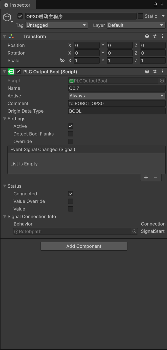
如你所见,我在用s7接口时出现了一点问题,我在S7-PLCSIM Advanced运行我的PLC时修改这一个值可以映射进unity,但是在unity中我尝试切换value却无法保持值,他就像切换了一下,但是马上被改回去了,我的值默认是false,点击切换后会短暂的显示true,但是还是会变回false,这是为什么,我在博途监控表里修改值是可以映射在unity中的,值也能正常切换,允许来自远程对象的 PUTIGET 通信访间也是勾选的,包括完全访问权限和仿真支持块编译也是勾选了,博途设置也没有问题,就是unity无法切换博途v20的值,我使用的版本是realvirtual.io6.2.1,博途版本是v20
Customer support service by UserEcho

As you can see, I'm having an issue with the S7 interface. When I run my PLC on S7-PLCSIM Advanced, modifying this value allows it to be mapped into Unity. However, when I try to toggle the value in Unity, it cannot retain it—it switches briefly but immediately reverts back. The value is false by default; after clicking to toggle it, it briefly shows true but then goes back to false. Why is this happening? Modifying the value in the TIA Portal monitor table works fine, as it can be mapped into Unity and toggled normally. The option "Allow PUT/GET communication access from remote objects" is checked, and both "Full access rights" and "Compile simulation support blocks" are also checked. The TIA Portal settings seem to be correct; the only problem is that Unity cannot toggle the value in TIA Portal V20. The versions I'm using are realvirtual.io 6.2.1 and TIA Portal V20.
Hi, this is a PLCOutputBool so it is going from the PLC to Unity. You can only toggle from Unity Side PLCInputBools (which are signals from Unity to PLC).
Okay, thank you for your reply. I just got confused for a moment.
By the way, I have a few more questions. When I connect via Advanced, when PLCInputBools modifies PLCOutputBool, there is a switch in Unity, but the signal does not switch. Moreover, in TIA Portal, the signal sometimes switches to true and then switches back to false. Could you help me figure out the reason for this?
can you explain a little bit more. What is exacly your setup - how is a Input modifying the output?
My setup is Unity (realvirtual.io) connected to PLCSIM Advanced.
I can change the Input area (I) from Unity, and the change is visible in TIA Portal.
However, the Output (Q) does not change automatically.
I have learned that in Siemens PLCs, an Input does not directly modify an Output unless the program in TIA Portal explicitly contains this logic.
So if I want an Input signal to drive an Output, I need to add logic in TIA Portal, for example:
Without this kind of logic, simply changing an Input will never make the Output change.
Could you please confirm if my understanding is correct: that linking Inputs to Outputs always requires explicit logic inside the PLC program?
This is usually like this in all automation systems. Outputs and Inputs are clearly separated (also for security reasons). You can only write to outputs and read inputs on a PLC or RobotController.
Hi, this is exactly what a PLC is used for. There is a logic inside the PLC to react on Inputs and based on custom logic set the outputs. There is no real use case for an Input directly setting an Output. If you need some more deeper PLC Knowledge we have partners providing custom online training.
Hi, I have another question. Why is it that when I try to configure my signals like in the Game4Automation tutorial, after connecting to TIA Portal and starting the virtual simulation, the values sometimes aren't written properly? They switch signals briefly—like when I select "Value" and "Value Override" in Unity, the PLC only shows "True" for a moment before switching back to "False". But when I switched signals yesterday, it worked normally; today it’s back to this issue. I'm using InputBool, by the way. Sorry for asking so many questions.
Honestly I don't kow in detail your setup so hard to answer. For sure there is no a very basic bug in our interface. PLCInputs are purely for writing to a PLC, PLCOutputs are purely for getting signals from a PLC. Sometimes PLC code or hardware inputs are overwriting values if wrongly configured but it is hard to give a detailed answer based on your setup.
Okay, I understand that in Siemens PLCs the Input area (I) is normally read-only and should not be written from outside.
However, when I use PLCSIM Advanced together with Sharp7 (via realvirtual/Game4Automation), I sometimes see that I can temporarily write to Inputs from Unity — for example, the value switches to "True" for a short time before being overwritten again.
My questions are:
Is this behavior officially supported in PLCSIM Advanced, or is it just a side-effect of the simulation?
For stable and portable setups (especially when later connecting to a real PLC), should I always use M or DB addresses instead of I?
If the recommended way is M/DB, is there any official guideline or example for this workflow in digital twin applications?
Thanks for your help in clarifying this, I just want to make sure I’m following the correct and future-proof method.
Hi, an Input Area of a PLC is there to be written from the Outside (sensors, buttons or realvirtual in case of virtual commissioning).
To 1) maybe you did something wrong - you are able to clearly set signals which stay on the value from realvirtual.io. We provide realvirtual.io Support Hours for teaching you the basics if needed
To 2) there is no right way for doing it. Usually there is a company plc programming standard. from our side you can read and write to M, DB and to Inputs (only write) and Outputs (only read). The rest is up to you to decide depending what you want to do on the PLC side
To 3) No - realvirtual.io is made to support all possible customer standards. we are not experts in PLC programming, this is usually done on the side of our customers.