Teilen Sie Ihre Erfahrunge und Wünsche mit uns und anderen Usern!

 Read Node not getting values for arrays
Hello,
i´m using the OPCUA4Unity standalone package to communicate with my opc server.
Everything is setup correctly and i can connect to the server, import and read nodes.
Unfortunatly i cant get values for arrays though.
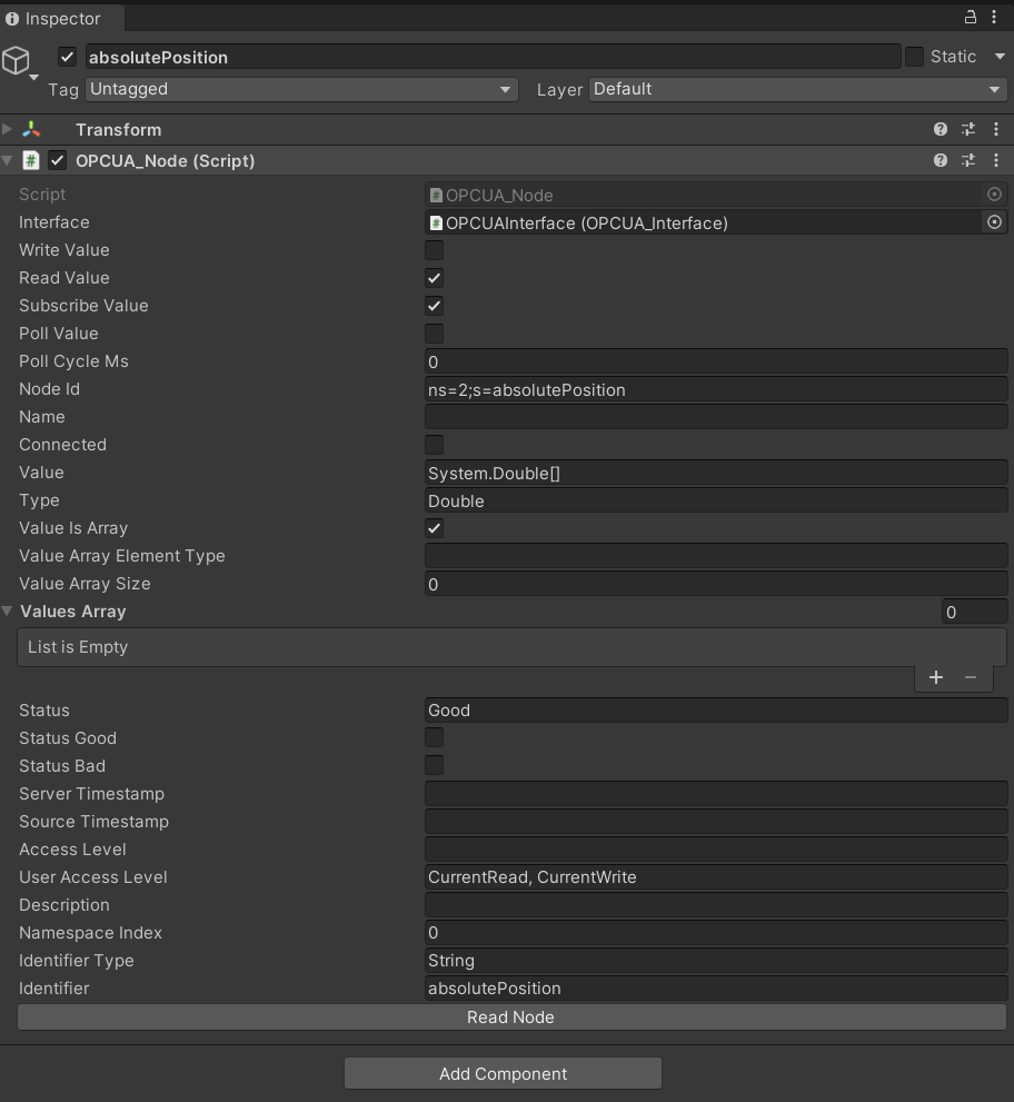
Example for the absolutePosition node:
The OPCUA_Node is recognizing that the node is an Array, but still wont fill in any actual values.
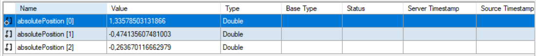
I doublechecked the values of the node using the OPCWatch tool:
I cant find anything related in the forums or the documentation.
How to handle arrays?
Kind regard
Mike

 I used mono build normally, but I used il2cpp incorrectly
D:\soft\2021.3.18f1c1\Editor\Data\il2cpp\build\deploy\il2cpp.exe @Library\Bee\artifacts\rsp\10185664654020197962.rsp
Error: IL2CPP error (no further information about what managed code was being converted is available)
System.AggregateException: One or more errors occurred. (The given key 'nop' was not present in the dictionary.)
---> System.Collections.Generic.KeyNotFoundException: The given key 'nop' was not present in the dictionary.
at System.Collections.Generic.Dictionary`2.get_Item(TKey key)
at Unity.IL2CPP.DataModel.Instruction..ctor(Instruction instruction)
at Unity.IL2CPP.DataModel.BuildLogic.Populaters.MethodBodyPopulator.CreateInstructions(CecilSourcedAssemblyData assemblyDef, MethodDefinition method, MethodDefinition source, ReadOnlyCollection`1 variables, Dictionary`2& instructionMap)
at Unity.IL2CPP.DataModel.BuildLogic.Populaters.MethodBodyPopulator.PopulateMethodBody(CecilSourcedAssemblyData assemblyData, MethodDefinition method, MethodDefinition source)
at Unity.IL2CPP.DataModel.BuildLogic.Populaters.DefinitionPopulater.PopulateMethodDefs(CecilSourcedAssemblyData assemblyData, TypeDefinition typeDef)
at Unity.IL2CPP.DataModel.BuildLogic.Populaters.DefinitionPopulater.PopulateTypeDef(TypeContext context, UnderConstructionMember`2 type)
at Unity.IL2CPP.DataModel.BuildLogic.DataModelBuilder.b__13_1(UnderConstructionMember`2 typeDef)
at System.Threading.Tasks.Parallel.<>c__DisplayClass44_0`2.b__1(IEnumerator& partitionState, Int32 timeout, Boolean& replicationDelegateYieldedBeforeCompletion)
--- End of stack trace from previous location ---
at System.Threading.Tasks.Parallel.<>c__DisplayClass44_0`2.b__1(IEnumerator& partitionState, Int32 timeout, Boolean& replicationDelegateYieldedBeforeCompletion)
at System.Threading.Tasks.TaskReplicator.Replica`1.ExecuteAction(Boolean& yieldedBeforeCompletion)
at System.Threading.Tasks.TaskReplicator.Replica.Execute()
--- End of inner exception stack trace ---
at System.Threading.Tasks.TaskReplicator.Run[TState](ReplicatableUserAction`1 action, ParallelOptions options, Boolean stopOnFirstFailure)
at System.Threading.Tasks.Parallel.PartitionerForEachWorker[TSource,TLocal](Partitioner`1 source, ParallelOptions parallelOptions, Action`1 simpleBody, Action`2 bodyWithState, Action`3 bodyWithStateAndIndex, Func`4 bodyWithStateAndLocal, Func`5 bodyWithEverything, Func`1 localInit, Action`1 localFinally)
--- End of stack trace from previous location ---
at System.Threading.Tasks.Parallel.ThrowSingleCancellationExceptionOrOtherException(ICollection exceptions, CancellationToken cancelToken, Exception otherException)
at System.Threading.Tasks.Parallel.PartitionerForEachWorker[TSource,TLocal](Partitioner`1 source, ParallelOptions parallelOptions, Action`1 simpleBody, Action`2 bodyWithState, Action`3 bodyWithStateAndIndex, Func`4 bodyWithStateAndLocal, Func`5 bodyWithEverything, Func`1 localInit, Action`1 localFinally)
at System.Threading.Tasks.Parallel.ForEachWorker[TSource,TLocal](IEnumerable`1 source, ParallelOptions parallelOptions, Action`1 body, Action`2 bodyWithState, Action`3 bodyWithStateAndIndex, Func`4 bodyWithStateAndLocal, Func`5 bodyWithEverything, Func`1 localInit, Action`1 localFinally)
at System.Threading.Tasks.Parallel.ForEach[TSource](IEnumerable`1 source, Action`1 body)
at Unity.IL2CPP.DataModel.BuildLogic.Utils.ParallelHelpers.ForEach[TSource](IEnumerable`1 source, Action`1 func, Boolean enableSerial)
at Unity.IL2CPP.DataModel.BuildLogic.DataModelBuilder.PopulateCecilSourcedDefinitions(ReadOnlyCollection`1 assemblyData)
at Unity.IL2CPP.DataModel.BuildLogic.DataModelBuilder.Build()
at Unity.IL2CPP.Contexts.Components.DataModelComponent.Load(LoadSettings loadSettings, Boolean ownsTypeContext, Boolean ownsBuilder, DataModelBuilder& builder)
at Unity.IL2CPP.AssemblyConversion.Phases.InitializePhase.Run(AssemblyConversionContext context)
at Unity.IL2CPP.AssemblyConversion.Classic.ClassicConverter.Run(AssemblyConversionContext context)
at Unity.IL2CPP.AssemblyConversion.AssemblyConverter.ConvertAssemblies(AssemblyConversionInputData data, AssemblyConversionParameters parameters, AssemblyConversionInputDataForTopLevelAccess dataForTopLevel)
UnityEngine.GUIUtility:ProcessEvent (int,intptr,bool&)

 TwinCat HMI Interface | Error in Connection
Hallo!
Ich wollte wissen, ob jemand Erfahrung im Umgang mit dem TwinCat HMI Interface hat, insbesondere mit Einstellungen die man eventuell im TwinCat Projekt vornehmen muss.
Ich habe zur Zeit das Problem, dass ich mit dem realvirtual TwinCat HMI Interface keine Verbindung zu meinem HMI Server herstellen kann. Über TwinCat ADS klappt es.
TwinCAT HMI | realvirtual.io User Documentation Die Einstellungen die hier vorgegeben werden, sind bei mir genauso.
Deswegen frage ich mich, ob es vielleicht an Einstellungen in meinem TwinCat Projekt liegt, also z.B. SSL/TLS verwenden oder nicht usw.
IL2CPP erro
Exception: IL2CPP error for method 'UnityEngine.Quaternion game4automation.IKCalculator::(UnityEngine.Quaternion)' in assembly 'D:\ZhangKang\IA_dev\Temp\StagingArea\Data\Managed\ikcalculator.dll'
System.NullReferenceException: Object reference not set to an instance of an object.
my unity version is 2020.3.33。 I've been dealing with this problem for too long and don't know what to do。please help me

Difference between grip (script) and fixer
Hi,
first I would like to tell that I really like realvirtual.io and and simulation possibility and openness it provides. But at the same time it's often so frustrating because it's kinda challenging.
Now I got the following problem.
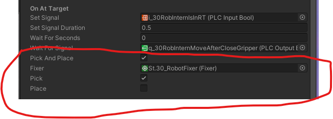
I want to use the new fixer pick and place function in IKTarget.
I have two robots and a round table with 4 grip scripts.
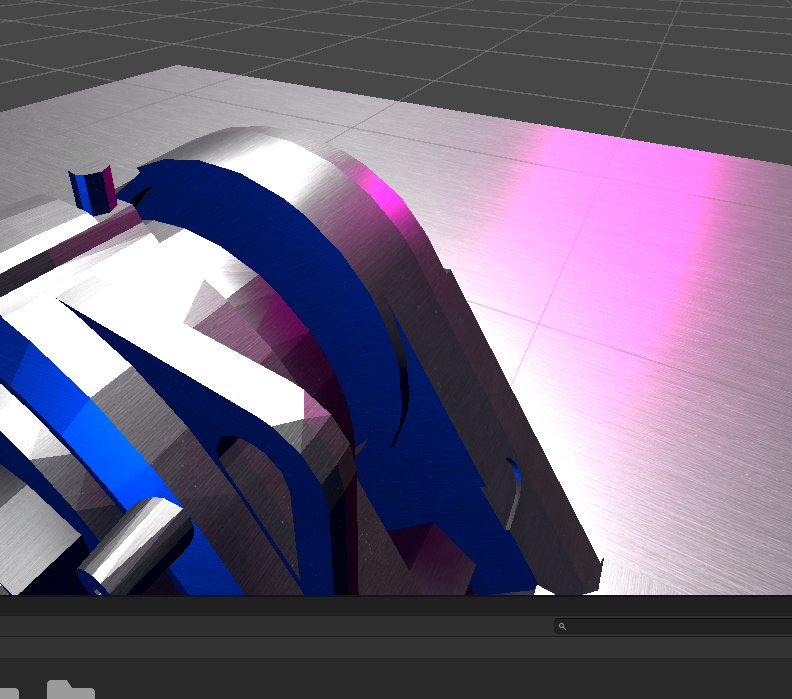
Overall view:
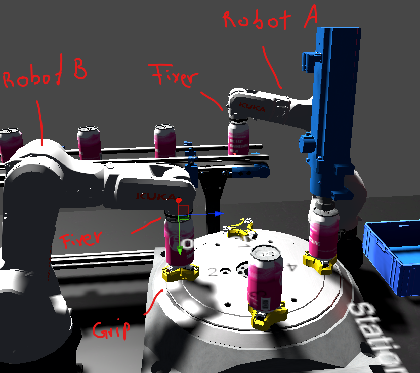
Robot A takes the MU with fixer pick and places it on the RT. The RT picks it up with a grip script and it's fixed by the gripper.
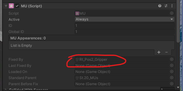
But robot B can't pick up the MU from the round table. It seems to fail because of this code line in fixer script:

If I delete this line than the pick up by robot A isn't working because for some reason the fixer script of robot A does list the MU two times in MUS Entered. (I guess it's the reason)
2 Questions:
1. Where is the difference between grip and fixer?
2. How can I make the pick up work by robot b fixer pick?
Best regards
Andreas

In the scenario you described, it seems that the MUs are being simultaneously gripped by two different components. This isn't supported or intended behavior. Typically, when something is gripped or fixed, it becomes a child of the gripper or fixer, following its position. If Gripper A moves while Gripper B is still gripping, there’s a conflict—who will control the movement?
This is likely why your case 3 isn't working. Such a setup could lead to unexpected behavior, potentially causing collisions or damaging other elements that rely on the Grip/Fixer system. I recommend developing a custom gripper tailored to your specific needs to avoid these issues. But we are taking this into account if we think about reengineering Grip or Fixer in the future.
I will also extend our documentation to make sure that it is clear that gripping one part by two Fixer or Grip is not supportet.

How to set correct position for roatation kinematic on axis
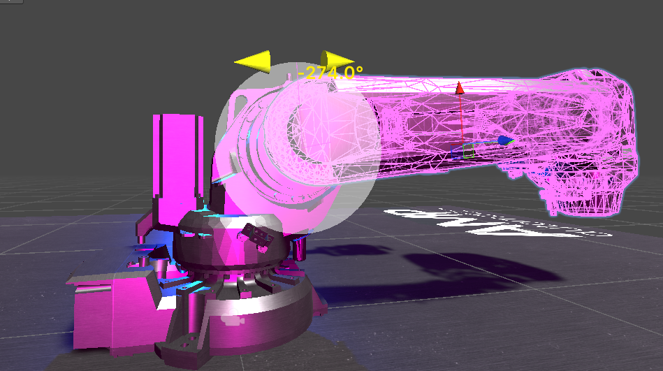
While trying to setup the demo robot I have found that you must manually place the drive in the dead centre of the axis for the point of rotation although it seems extremely hard and inefficient to have to manually set this and try get right?
Is there any methods or tools to use to get the point of rotation in the dead centre, I will put some photos to try visualise
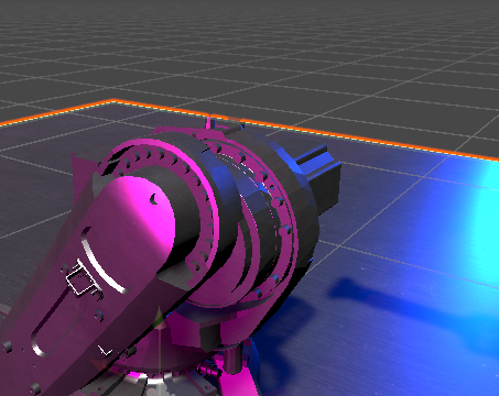
what I mean

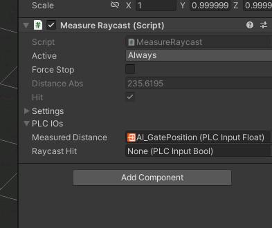
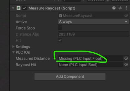
plc input disappear in
Hello,
I created a Measure Raycast and linked with PLC Input Float, but when I start simulation the tag disappear and does not
communicate with PLC.
How can I fix?
Thanks!

Handing over MU between two grippers
Hi,
how to solve the following problem in handing over situations:
- gripper 1 grips MU. MU is now attached to gripper 1
- some transfering is done
- gripper 2 grips MU. MU is gripped by gripper 1 and gripper 2. MU is now attached to gripper 2
If gripper 2 opens now, the MU is no longer attached to gripper 2 and falls down.
What I want to achieve is:
Gripper 1 is still closed and the MU should now be attached to gripper 1 again.
How can I solve this?

About the most package
您好,由于我更新 Professional 2022.15版本后报错,项目无法正常进行下去,并且unity包管理器里面没有历史版本下载2022.13,导致我无法进行工作,我已经给邮箱发送我的发票号但是没有收到关于Professional 2022.16 and Simulation 2022.16回复, 请您有空发送邮箱给我2022.13或2022.16的Professional和Simulation 的包。
十分感谢。
Customer support service by UserEcho
